A company's operational efficiency is intimately tied with the organization of existing building data and documents. Whether facility services are outsourced or managed by in-house staff, a company's facility data and documents can be conveniently organized and effectively used with a parametric digital model. Facility Management (FM) is rooted in service relationships and Building Information Modeling (BIM) revolves around digital construction and manipulation of real estate asset data. Seemingly world's apart, in the long term both FM and BIM will have a significant effect on the life cycle cost savings and holistic sustainability of real estate assets. When used in conjunction both FM and BIM have an extremely high potential in optimizing space scheduling and workplace efficiency.
For true success BIM must be a fully collaborative effort which highlights the importance of property owner coordination.
A facility can be thought of as anything which facilitates business; facility management is accurately understood as a mix of service relationship management with real estate asset management. Facility Managers focus on service management in a way that best supports a company's primary business processes. This allows FM to align a company's strategic objectives with its operational activities
Building Information Modeling can be thought of as a real time data communication platform and evolutionary workflow. A Building Information Model is a digital product that can be continuously updated to reflect the current state of real estate assets. In an step towards environmental stewardship, this year (2016) the United Kingdom government has mandated a Level 2 BIM be used for the construction and management of all new government building projects. Currently in the United States of America, BIM is most prominently used by general contractors to coordinate complex building construction projects.
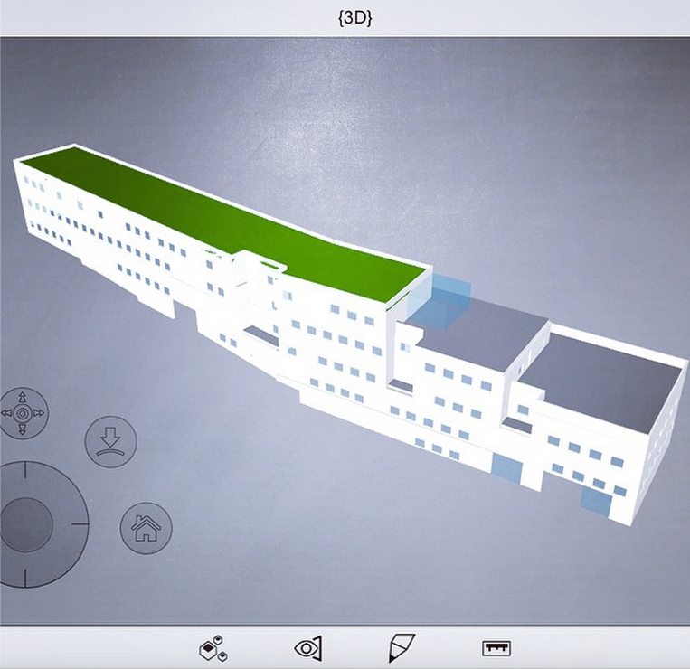
Building Information Models Such As The One Shown Above, Will Be Accessed Remotely On Smart Phones And Tablets By Facility Managers To Find Reliable Asset Information (E.G. Warranty Information, Repair Manuals, Installation Dates, 2-D Floor Plans, Etc.) For Improved Operational Efficiency And Optimal Decision Making.
To be most effective in the construction phase, BIM must be a fully collaborative process which highlights the importance of property owner coordination. Considering the majority of facility life cycle costs are incurred during the operational phase of buildings, FM BIM has the potential to make the highest impact on an owner's cost savings. Cost savings from FM BIM will come in the form of minimized redundancy when locating accurate and reliable facility data during the real estate asset management life cycle phase. Monitoring workplace comfort and security is another highly valued benefit of having a real time digital model to support operations.
To learn more contact BIM Specialist, Leo Castillo
posted May 18, 2016 in [field_categories]

CAMPBELL, CALIFORNIA
SANDIS Civil Engineers Surveyors Planners announced today that it is expanding their Building Information Modeling (BIM) and 3D Laser Scanning capabilities by the acquisition of Consulting Technical Services Incorporated (CTS).
Headquartered in Pleasanton California, CTS was founded by Leo Castillo in 2012 and specializes in BIM, 3D Laser Scanning and As-Built Solutions for the Architecture, Engineering, Construction, and Facility Management industries.
“I started CTS because there are incredible benefits to be realized using 3D Laser Scanning and BIM as a basis for Design & Construction and I want to help customers realize the value of these methods to deliver better projects” said Castillo.
CTS’ experience extends across the United States and Canada and reaches numerous sectors such as High-Tech, Manufacturing, Commercial, Retail, and Medical. CTS is actively working on projects for Apple, Google, Microsoft, Facebook, Hyatt, and has worked on projects for Intel, Costco, and Kaiser.
CTS will continue to maintain its existing name and brand. Leo Castillo will remain as President of CTS and manage all operations. “For our existing and future customers it’s business as usual if not better” said Castillo.
SANDIS has been providing 3D laser scanning and BIM services for over six years and has recognized and responded to the extreme growth and demand for these professional services.
President, Ken Olcott and Vice-President, Jeff Setera spearheaded the acquisition of CTS. “We can now provide end-to-end and complete vertical solutions to our Clients” said Olcott.
Contact
Evan Miller
Marketing Manager
SANDIS & CTS
510.590.3411
emiller@sandis.net
marketing@newcts.com
posted February 1, 2016 in [field_categories]

Introduction
Traditional methods for collecting as-built measurements, primarily measuring tapes, hand-held lasers, and tape wheels are still relatively useful for small-scale applications where line-of-sight is maintained at all times. However, when a high-degree of accuracy is required; whether to verify confidence in a design, or when the application is a multi-level, large-volume environment there are significant advantages found in using high-capacity 3D laser scanning for reducing errors and omissions, reducing as-built collection time, and even aiding the design phase by providing 3D images and over-the-web access to the project site to extended/remote design teams.
“The Last Five Years Has Brought An Explosion In Market Growth Of 25-30% For Laser Scanning Technology,
Even Through A Recession.”
For all intents and purposes 3D laser scanning is not a new technology, with a form of laser scanning being introduced in the late 1970’s by Canada’s National Research Council. Fast forward to the last five years which has brought an explosion in market growth of 25-30% for laser scanning technology, even through a recession. This market demand for high-precision measurement capture has almost outpaced advances in the technology itself, resulting in a renewed push to develop and supply more rapid, compact and mobile scanning equipment to serve ever expanding market applications including:
- Architecture, Structural & Civil Engineering
- Commercial & Retail Property Management
- Entertainment & Gaming
- Food & Beverage
- Law Enforcement & CSI
- Manufacturing
- Medical Research
- Oil, Gas & Renewable Energy
This kind of market demand has contributed to achievements in simplifying the laser scanning process over successive scanner generations. Some of the current generation scanners even resemble the ease-of-use and size of modern-day professional digital and video cameras. One scanner manufacturer in particular (Faro) has experienced considerable success by combining a light-weight form factor with a friendly touch screen user-interface. With an experience that can be compared to using a modern touch-screen mobile phone, the scanner even allows operation remotely via the built-in WiFi. This has been incredibly useful for enabling operation of the scanner even when the scanner itself is placed in remote, congested or dangerous environments.
The Scanning Process
Due to advances in technology the scanning process has become quite simple. The scanner is securely placed onto a construction-grade tripod and integrated sensors are calibrated for Northing (Compass), Level (Dual-Axis Compensator) and Height (Altimeter). The scanner is started and begins to emit a laser beam from a rotating mirror out towards the scanning area in a vertical and horizontal pattern at an approximate rate of 500,000 points per second. The laser beams reflects back from the objects within its field-of-view back to the scanner, which then calculates the distance, relative vertical and horizontal angles to the measured objects, while recording these critical measurements to the on-board SD card:
- Height / Elevation / Z-coordinate of the measured point
- Northing / Y-coordinate of the measured point
- Easting / X-coordinate of the measured point
Along with detailed measurements, the scanner records 360-degree, high-definition images and generates a consolidated 3D image by analyzing, cross-referencing then appending the red, green, blue values (RGB) from the images to the million+ point database. This last step is arguably what makes laser scanning one of the most powerful, and effective as-built documentation methods available today. As the saying goes “a picture is worth a thousand words”, then a 3D image which effectively captures the existing conditions in incredibly high detail must be priceless. The precision and resolution from the 3D scan empowers the end-user to verify dimensions and measure distances from the comfort and safety of the office environment. Existing buildings, structures, mechanical and process equipment are now recordable, storable and viewable on standard computer networks or storage devices in a digital form like never before. The question then becomes what you can do with this wealth of information after the 3D laser scan is complete.
With An Experience That Can Be Compared To Using A Modern Touch-Screen Mobile Phone, The Scanner Even Allows Operation Remotely Via The Built-In WiFi
If the end-user is primarily interested in fast and immediate access to this high-quality as-built information, there are three basic options outlined here. A service provider could specifically recommend different options depending on the client’s unique circumstances, end goals and facility management plan/software in place. Upon scan completion:
1. Receive and store the data on a local network and refer to the point cloud and pictures using freely available software programs such as Faro Scene LT (http://www.faro.com/focus/us/software).
2. Request that your service provider convert and provide the data in a CAD or BIM-based point cloud format such as Autodesk’s PCG which allows further, more advanced “vertical” processing of the scan data in programs such as AutoCAD, Revit, Civil 3D and Plant 3D.
3. Request that your service provider host the scan data and make it available via the internet (http://newcts.com/webshare/) by providing a password-protected login which enables remote viewing, measuring, downloading and sharing of the scan data amongst stakeholders.
CAD Implementation
Based on the age of the facility, the quality of reference information facility managers rely on for critical decision-making can vary greatly from outdated hard-copy plans – with wide-ranging degrees of accuracy – to no plans at all. Supplementing and improving this form of as-built information can require constant and extensive field visits, tape and hand-held laser measurements, as well as photography to properly document onsite assets and their locations. It goes without saying that there are significant inefficiencies with this legacy system of facility management, not to mention risks associated with personnel spending ever-increasing time in the field, and risks to project budgets/schedules because of a lack of facility-wide and/or project specific as-built documents.
CAD software has provided some measure of relief to this problem by requiring as-built measurements to be taken and documented far less frequently by drawing and recording measurements in a digital form, then allowing distribution of electronic drawings far more frequently to a larger audience. However, even this improved system greatly depends on the quality of the as-building data collection process used. Considerable person-hours have been spent developing and maintaining plans and drawings which are then used for facility master planning, project management, procurement and construction administration only to find out during construction (usually after significant cost overruns) that the drawings were no more accurate than if they had been hand-drafted in the first place. This is not necessarily a personnel problem, but more likely due to the limitations of traditional methods of as-building and documentation when applied to large-scale facility or project mapping. A better solution is necessary and laser scanning embraces the access and documentation benefits of CAD systems, while vastly improving the data-collection process.
Numerous organizations have embarked on, or directed their consulting engineer/integrator to develop and implement a comprehensive facility mapping and as-building program. The initial up-front cost investment required can be significant, but is usually budgeted as capital expense, or executed in a phased manner, or even designed as a modest pilot project until expected return-on-investment benefits are realized, thereby justifying expansion of the facility as-building program into a large-scale effort.
Recent news regarding CAD-software leaders such as Autodesk and Bentley making outright purchases of laser scanning software companies signals a precursor to a significant marketing push for CAD users to solve the as-built documentation problem by training on implementing point cloud data within existing workflows. Since version 2010, Autodesk has been educating users on how to import point clouds as a reference for drafting line-work to represent as-built conditions. Autodesk has even revealed plans to rewrite the AutoCAD software to better implement point cloud technology.
Applications
As mentioned at the outset, applications for laser scanning and 3D data capture continue to expand but are primarily focused here on four aspects of the design-construction process:
Architecture: Retrofit and remodel of existing structures, high-end buildings, or buildings of historic significance require thorough as-built documentation in order to establish exact limits-of-work, interface points, and ultimately ensure a seamless product at completion. Utilizing laser scanning to document the location and condition of remaining walls, doors, windows, penetrations, façade details, staircases, etc. provides an invaluable reference 3D image to ensure details large and small are not overlooked and are reflected flawlessly between the old and new. There have also been benefits reported when laser scanning new and high-end buildings at completion to document final move-in conditions as an archive to reference back to for future use in retrofit and remodeling. With the increasing adoption of Building Information Modeling (BIM), Autodesk Revit users can also import laser scanned point clouds at early stages of building the model to develop high-certainty concepts.
Engineering: Civil and structural engineering necessitates use of high-quality survey information to establish datum’s, benchmarks and control networks. 3D Laser scanning is quite naturally being incorporated into this workflow in order to bring survey-grade data into the facility environment, but at drastically shorter timeframes. Laser scanning is regularly used for location verification of structural beams and cross-members either pre-existing or immediately upon install to verify tolerances and/or deformities when they can be addressed in a cost-effective manner. An increasing cross-section of experienced engineer’s are requiring this high-quality information at the start of schematic or conceptual design stage to protect against errors and omissions later on in the timeline and to increase their own certainty that their proposed design is a workable solution. Structural engineers are able to deploy laser scanning to capture pre-existing structural members slated for upgrade or retrofit, import the as-built point cloud into structural modeling and load analysis software, then reverse-engineer load models for further analysis.
“Contractor To Verify Everything” Possibly The Most Overused Note In The History Of Construction Documents
Construction: “Contractor to Verify Everything” Possibly the most overused note in the history of construction documents; and for good reason. Contractors innately understand the risk for being left “holding the bag” for potential design errors and omissions in the contract documents they are bound to follow. Some of this can be addressed by skilled review and estimating during the bid process, but not all. Not content with placing full faith in wet-stamped construction documents (CD), upon contract award and immediately after “soft” demolition an increasing number of contractors are deploying laser scanning to quickly capture the project as-built conditions then perform a detailed comparison against CD’s to check for inconsistencies and significant oversights that could affect the viability of the design. With this advanced knowledge, contractors have the advantage of recognizing design problems before heavy construction, and then discussing contract changes orders with owners at a stage when the pressures of cost overruns and schedule delays are not present.
A second common application involves using laser scanning to assist in project value engineering (VE). In retrofit circumstances, there are instances when a design-team has only the benefit of assumed infrastructure and location in order to develop a proposal and is in need of actual verified as-built conditions in order to finalize calculations and also to determine whether existing infrastructure can be salvaged and reused. As integral members of the design-team, contractors can use laser scanning to capture the precise structural, MEP and building envelope conditions and provide back to the designer and owner to assess for VE and finalize design.
A third application for laser scanning is during construction administration (CA). Specifically when an overall project team has implemented a project Building Information Model (BIM), laser scan point clouds can be used with the BIM using construction management and visualization software during meetings to review construction activities, phasing, staging, verify for clashes and generally develop a thorough plan of action with owners, designers, stakeholders and contractors.
Finally, laser scanning is proving invaluable as a long-term reference by rapid scanning of key obscured infrastructure immediately after final installation, but prior to permanent encasement of underground utilities, steel and concrete foundations, rebar reinforcement, etc. These 3D images and point clouds are then stored and available in perpetuity for recollection at future retrofit and remodel.
Facility Management: Owner-operators routinely rely on the engineering and construction services of consultant firms for expansion and capital improvements of facility assets. Many factors affect whether the existing facility management program includes proper maintenance of true record as-built plans/drawings including the age of the facility, investment of IT infrastructure and FM personnel, and even the nature of the business sector the owner-operator competes in can determine likelihood of adoption of new technology and best management practices.
Many consultant firms however, as a good standard of practice, incorporate a thorough and exhaustive documentation and verification phase of existing site conditions into their design process. Whether at conceptual design or prior to final engineering and irrespective of budgets, 3D laser scanning affords facility managers to efficiently undertake (or request) as-building of critical infrastructure before, during and/or immediately after project retrofit and improvement. Laser scanning can be applied to large, expansive upgrade projects (usually incorporating traditional survey methods for control), as well as to smaller area specific upgrade projects. In either case, when requiring use of laser scanning, facility managers are increasing their confidence that the proposed improvement plan will work without major and costly conflicts due to unforeseen, improperly verified, or undocumented project site conditions.
Return-On-Investment Benefits
The following are the key economic benefits which were outlined in a research document studying the perceived vs. realized paybacks when applying 3D laser scanning to industrial plant design, capital improvement projects, and operation maintenance expenses. They are cited here without modification:
Risk mitigation: All industries experience rogue projects where cost, schedule or safety has spiraled out of control due to incomplete or incorrect as-built documentation or inadequate dimensional control procedures. Laser scanning workflows have proven beneficial for reducing project risk on brownfield projects, particularly where energy densities are high; site access is difficult or expensive; modular design and fabrication methods are deployed; and project schedules include acute sensitivities.
Cost and schedule reduction: Laser scanning has reduced total installed cost for brownfield projects by 5-7% and has reduced contingencies for rework to less than 2% compared to traditional survey methods. These results are remarkable not only for the magnitude but for their consistency across a wide variety of projects. Achievement of these cost savings sometimes requires higher initial investment in 3D data capture solutions than traditional methods (total station, piano wire, spirit level, plumb bob and tape measure). Schedule compression of as much as 10% has been reported when 3D laser scanning has been deployed. Such savings dwarf the cost of data capture and modeling in applications such as nuclear power generation where outage time costs $1 million/day and offshore platform revamp production values can exceed $500,000 per day.
Safety and regulatory compliance: Owners are subject to increasing governmental scrutiny and regulation which demand the creation and upkeep of not only the as-built but as-maintained condition of production assets. Laser scanning is increasingly used to comply with health, safety and environmental imperatives. Compared to manual data capture methods, laser scanning methods are often safer. The remote sensing ability of today’s scanning systems and their rapid data capture means reduced jobsite exposure. Offsite fabrication methods, safer where hot work permits are required, can be used with confidence when adequate dimensional control ensures bolt-up installation instead of onsite welding.
Improved quality and other benefits: Complete and accurate dimensional documentation based on laser scanning has resulted in myriad collateral benefits ranging from the ability to perform better simulation of asset and equipment performance for training purposes, better visualization to coordinate multiple engineering disciplines and craft construction, better visualization to secure project funding, more analytic and quantifiable construction monitoring, and more flexibility to accommodate scope change.
Conclusions & Recommendations
Full-scale adoption of laser scanning and point cloud technology is on the immediate horizon for Architecture, Engineering, Construction and Facility Management professionals. Also the costs of 3D laser scanning hardware and services continues to decrease which means increased market adoption, an increased demand for software, visualization, and sharing tools to use this rich information.
Full-Scale Adoption Of Laser Scanning And Point Cloud Technology Is On The Immediate Horizon
Even if nothing else changes, the software which designers, contractors and facility managers use and make annual investments in will be altered (or has already been) to take advantage of valuable laser scanning data. This may be the right time to look at existing process and workflows to determine if adoption of laser scanning can improve business efficiencies.
Evaluate Costs:For those on the “fence” on whether to purchase a scanner vs. hiring the services of a laser scanning provider, it takes relatively little effort to consult with an experienced service provider to discuss their experience addressing the challenges and costs associated with laser scanning including:
1. Hardware costs (i.e. scanners, server storage space, new computer workstations or upgrades
2. Software costs for licenses of CAD, scanner, and other point cloud processing & analysis software
3. Employee costs for hiring or establishing dedicated scanning/as-building personnel
4. Training costs to ensure successful implementation of investment in laser scanner equipment
With this basic information, it would be feasible to evaluate if individual business circumstances dictate whether absorbing the upfront costs of laser scanning or subsidizing the services of a laser scanning provider as pass-through expenses to the project would profit the business greater.
If opting to subcontract laser scanning services, select a provider who either includes or is willing to provide some measure of training along with scanning services. This will ensure the end-user(s) will “train up” toward potentially investing in laser scanning equipment at a later date.
Start Small: If you are a facility manager interested in exploring the possible purchase of a scanner, or maybe your primary goal is to modernize facility management workflows/methods and ultimately improve the understanding of existing assets under your responsibility. We recommend starting small. Identify an order-of-magnitude priority list of assets that would likely benefit from high-precision as-building by 3D laser scanning.
Whether selecting assets slated for scheduled upgrades soon, or assets that have high-maintenance costs or are low-production; having a clearly defined scope for your service provider will make integrating laser scanning into your workflows much more efficient. Simply directing your service provider to “scan everything” is not a recipe for success.
Status-quo unsustainable: Given the high-precision, ease-of-use, reduced cost, increased availability, and broadly-used CAD software adoption, many companies have concluded there is little comparison between 3D laser scanning and traditional “as-built” measurement methods using tape measures, laser range finders, and digital cameras. Large-volume laser scanning provides safety, cost savings, and the accuracy professionals should consider implementing sooner rather than later to stay competitive.
Frequently Asked Questions (FAQ’s)
Q How much does scanning cost?
A Many factors affect laser scanning costs including the type project and assets being scanned, but the general range can be between $0.25 to $1.00 per square-foot.
Q How long does scanning take?
A The rule of thumb for laser scanning duration is about 5,000-10,000 square-feet per day. This of course depends on the type of scanning project and the complexity of the area to be scanned. Generally, laser scanning duration and costs increase as shown in the chart to the right.
Q Can the scanner see through objects?
A No. 3D laser scanners are line-of-sight machines. Through a network of control spheres, and using the scanner in numerous strategic positions, a more complete scan product can be achieved.
Q Does the scanner work indoors and outdoors?
A Yes. There are various types of scanners that work indoors and outdoors. Some are better suited to interior environments while others are more suitable for open-air environments. It is our opinion that the FaroFocus3D offers the best combination of features, ease-of-use and value for a large cross-section of indoor and outdoor applications.
Q How far away can the scanner measure?
A The scanner can comfortably measure up to 120 meters (~400 feet) although the further away from the scanner, the lower the resolution (less dense) the point measurements will be. An experienced service provider will develop a comprehensive scanning plan and will factor in the scanning distance when setting the scanner resolution settings.
Q How precise is the scanner and resulting point cloud?
A Each individual scan point collected ranges between 1mm and 5mm (~1/8-inch) depending on the distance from the scanner, angle to the scanner, and surface reflectivity. The closer the scanner is placed to the objects requiring scanning, the more dense and accurate measurements will be.
Q Can the scanner and point cloud be matched to our facilities coordinate system, datum and/or grid?
A Yes. If the facility maintains a control grid, visible benchmarks can be scanned and coordinates assigned during post-processing of the scan data. Alternately, a CAD plan can be used to align the scan to the proper location within the facility.
Q What can I do with the laser scan and point cloud once I have decided to use it for my project or facility?
A See the Applications section of this document for a more detailed discussion of this topic.
Q Why isn’t everyone doing this on every project?
A There are 4 primary reasons laser scanning is not implemented on every industrial plant project:
1. Lack of awareness. The worldwide population of working 3D laser scanners numbers fewer than 5,000 units. Though the market has grown 25-30% over the past five years and continues to expand, even through the teeth of a recession, it is still early in the adoption cycle.
2. Perceived cost. For some projects, traditional methods are more cost effective. The challenge is to understand when it makes sense to make the leap.
3. “Old Way” mentality. Changing work flows is often painful. To get full value for laser scanning, organizations often need to embrace 3D and abandon familiar 2D processes.
4. Integration challenges. While some of today’s plant design solutions have embraced point cloud integration, notably products from AVEVA, Bentley, COADE and Intergraph, many have yet to do so.
Glossary
The following definitions have been gathered from various sources, some of which have been listed. The definitions associated with the ASTM are further obtained from various standard documents developed by various standards development organizations. The ASTM provides more in-depth discussion of several terms that have not been disclosed here; please refer to Designation: E 2544 – 08b, “Standard Terminology for Three-Dimensional (3D) Imaging Systems” for more details.
3D imaging system: A non-contact measurement instrument used to produce a 3D representation (for example, a point cloud) of an object or a site. (ASTM)
3D laser scanning: The process of collecting 3D coordinates of a given region of an object surface automatically and in a systematic pattern at a high rate (hundreds or thousands of points per second) achieving the results (i.e. 3D coordinates) in (near) real time.
Alignment: The process of aligning two objects in a common coordinate system. Commonly refers to aligning scan data.
As-built: Describes how a structure was actually constructed. The as-built condition of a structure may vary significantly from the design.
As-is: Describes the current status of the structure at present.
Azimuth: The angular distance measured along the horizon. Typically measured as the angular distance east from north.
Base station: In the context of external land surveying, a base station is a GPS receiver at an accurately-known fixed location which is used to derive correction information for nearby portable GPS receivers. This correction data allows propagation and other effects to be corrected out of the position data obtained by the mobile stations, which gives greatly increased location precision and accuracy over the results obtained by uncorrected GPS receivers.
Benchmark: A point of reference for a measurement.
Calibration: A set of operations that establish, under specified conditions, the relationship between values of quantities indicated by a measuring instrument or measuring system, or values represented by a material measure or a reference material, and the corresponding values realized by standards. (ASTM)
Clash-detection: Detecting possible collision between as-is and proposed design.
Control (see survey control)
Cross section: The intersection of a 3-dimensional body with a plane.
Dimensional Control: A risk mitigation process that is applied to every project execution task that requires a dimensional accuracy.
DEM (Digital Elevation Model): Digital stored xyz-triples of a surface. It is necessary to mention always which surface is meant by using the DEM (for example DEM of the ground water surface, DEM of the Earth’s surface).
DTM (Digital Terrain Model): Digital stored xyz-triples of the Earth’s surface. Therefore, the DTM is one special case of the DEM (DTM = DEM of the Earth’s surface).
Elevation: Angular distance measured from horizontal.
Error (of measurement): The result of a measurement minus a true value of the measurand (the particular quantity subject to measurement). (ASTM)
Facility Management (FM): An interdisciplinary field devoted to the coordination of space, infrastructure, people and organization, for business services functions such as offices, arenas, schools, convention centers, shopping complexes, hospitals, hotels, plants and warehouses.
Field-of-View (FOV): The angular extent within which objects are measurable by a device such as an optical instrument without user intervention. (1) For a scanner that is based on a spherical coordinate system, the FOV can typically be given by two angles: horizontal (azimuth) angle and vertical (elevation) angle. (ASTM)
Fly-through: In virtual reality environments, fly through is movement of an object or model through a predefined path.
Geo-referencing: Geo-referencing is the process of aligning spatial data (layers that are shape files: polygons, points, etc.) to an image file such as an historical map, satellite image, or aerial photograph.
INS (Inertial Navigation System): A navigation system that uses a computer and motion sensors (accelerometers and gyroscopes) to continuously track the position, orientation, and velocity of an object without the need for external references.
Instrument origin: The point from which all instrument measurements are referenced, that is, origin of the instrument coordinate reference frame (0, 0, 0). (ASTM)
LiDAR (Light Detection and Ranging): A method of detecting distant objects and determining their position, velocity, or other characteristics by analysis of pulsed laser light reflected from their surfaces.
MEP: Refers to the mechanical, electrical, plumbing/piping trade or infrastructure of a facility or project.
Mesh: A polygonal subdivision of the surface of a geometric model; also referred to as polygon model or triangulated model.
Meshing: The process of creating a 3D surface from point clouds.
Phase-based: 3D laser scanners that produce measurements based on intensity modulated, continuous wave laser beams.
Photogrammetry: The process of taking precise measurements by using digital pictures and coded targets. For 3D scanning purposes, the coded targets and reference markers in the picture frame serve as references to align or register scan data.
Point cloud: Laser scan data from multiple scan stations in a defined volume space. [A] collection of data points in 3D space (frequently in the hundreds of thousands), for example as obtained using a 3D imaging system. (1) The distance between points is generally non-uniform and hence all three coordinates (Cartesian or spherical) for each point must be specifically encoded. (ASTM)
Point density: Number of points per unit. Usually the higher the point density is, the better representation of features.
Raw scan data: Any unprocessed data collected by a laser scanner. This might include different sources of error and peripheral data captured during the scanning survey.
Registration: The process of determining and applying to two or more datasets the transformations that locate each dataset in a common coordinate system so that the datasets are aligned relative to each other. (ASTM)
Scan: Refers to a single session of data collection at a single scan origin and scan orientation.
Segmentation: The process of separating and isolating groups of points from the laser scan.
Soft-Demolition: Demolition of surface features such as drywall, cladding materials, reflected ceilings while leaving major structural and mechanical elements in place.
Survey control: The point(s) of reference where all measurements for engineering and construction will be tied to.
TIN (Triangulated Irregular Network): Representation of a surface that is arranged in a network of non-overlapping triangles.
Time of flight: 3D laser scanners that calculate measurements based on the two-way travel time it takes for a laser beam pulse to detect a surface and return to the detector.
Uncertainty: The uncertainty is the quantity of how much a measurement is unknown compared to the actual feature.
References
1. Large-Volume 3D Laser Scanning Technology, Faro Technologies, 7/2012
2. 3D Laser Scanning: Benefits and Paybacks for Industrial Plant Design, Construction and Operation, Spar Point Research LLC, 11/2009
3. What is 3D Data Capture, Spar Point Research LLC, 12/2012
4. Lighting the Way – Best-practice business process for using laser technology on plant revamp projects, Aveva Business, 11/2012
posted March 10, 2015 in [field_categories]
What is the process for evaluating the suitability of land for potential open-space preservation, ecological restoration, or wetland mitigation banking? The first step is to call Geoff Smick and Justin Derby of WRA – a firm expert in environmental consulting since the 1980′s.
When WRA was interested in finding a non-intrusive, highly-precise method for capturing the physical condition of high-quality vernal pools in Northern California, they turned to CTS and 3D laser scanning.
CTS provided the initial consultation about 3D laser scanning best practices, with Meridian providing the field collection. Sometimes Mother Nature is the best designer, and in the coming weeks WRA will utilize the millimeter accuracy laser scan as a ‘blueprint” to inform the design of restored habitats.
Stay tuned for more updates as this Case Study develops.
posted March 10, 2015 in [field_categories]
As a leading owner, developer, and operator of Real Estate assets in the Greater Sacramento Area, D&S Development understands the need for accurate record information about their properties. So when it came time to begin a Tenant Improvement project at their 100,000+ sf Countryside Shopping Center, a lack of any Facility “as-built” plans or any reliable dimensional information whatsoever posed a significant challenge to the design team.
CTS was the solution they were looking for. After an initial consultation, CTS was rapidly engaged to provide the required “as-build” information and help maintain the project schedule. CTS deployed the Faro Focus3D for a rapid-scanning of the area, and brought the resulting point cloud into Revit to produce an accurate and verifiable 3D model to base the design-build from. “CTS introduced us to scanning technology and helped reduce the uncertainty in our plan,” said D&S Construction Manager Reza. “I suspect working with CTS will become SOP moving forward.”
posted January 28, 2015 in [field_categories]